Designing a Synchronous Logic Circuit
Project Conducted in the Logic Circuit Class
Multisim
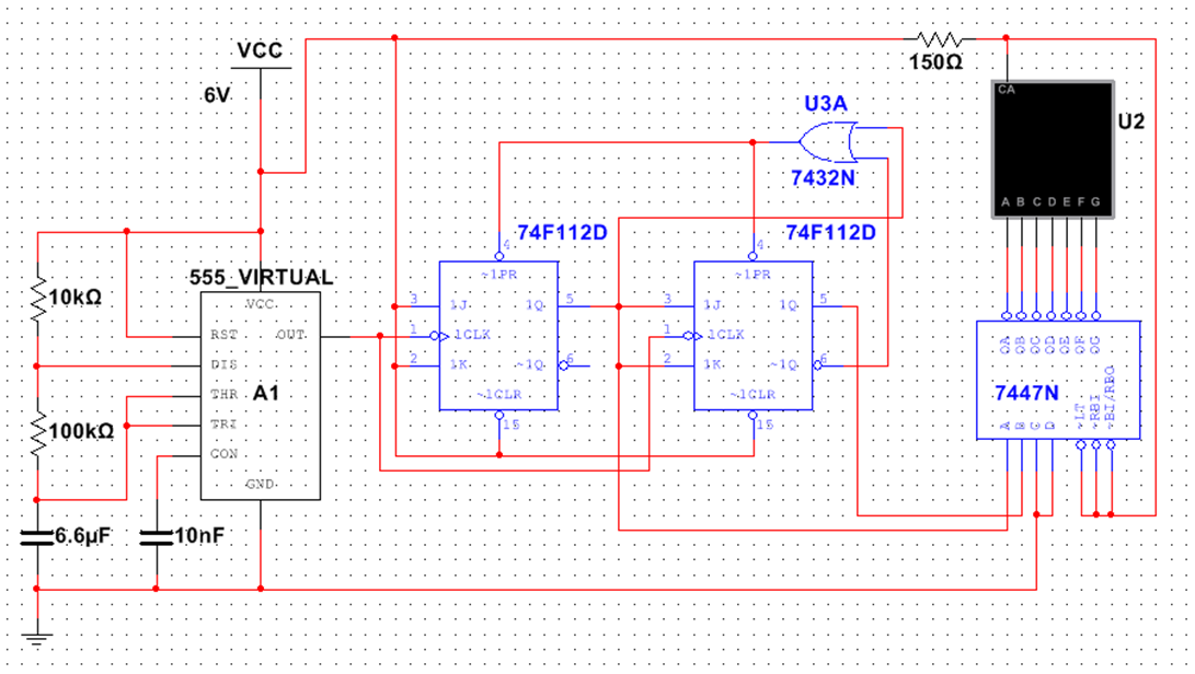
The goal of this project is to design and create a circuit using logic components and a 555-timer to sequentially display given numbers on a 7-segment display every one second. My numbers were 0, 1, and 3.
The circuit was implemented as an up-counter with a modulus of 3 using two negative-edge-triggered J-K flip-flops. When the counter outputs 2, both flip-flops are preset, as 3 is represented in binary as 11(2). An OR gate was used to output 0 by taking the Q of the first flip-flop and the ~Q of the second flip-flop as inputs.